precision in design starts here

Technical drawing and engineering drawings

Draft precise and detailed technical and engineering drawings quickly with CAD software from Autodesk.

Technical drawings using AutoCAD
A technical drawing created in AutoCAD

What are technical drawings and engineering drawings?

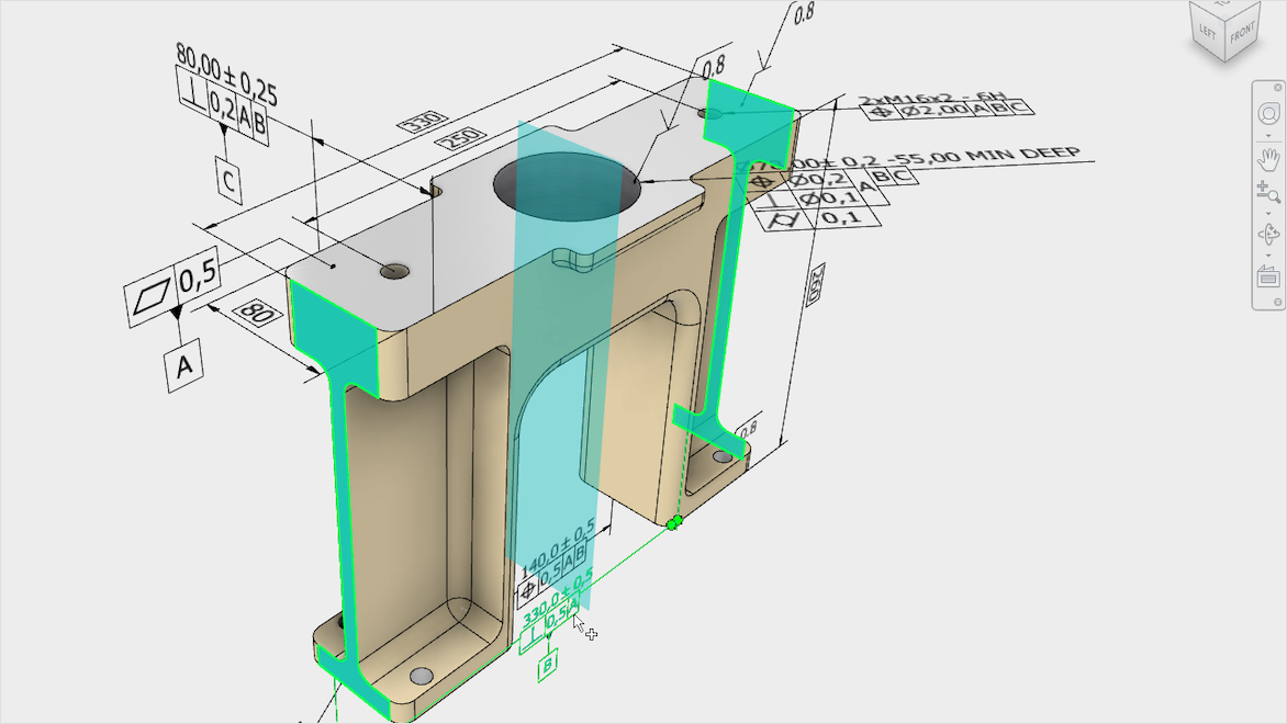
By definition, a technical drawing—also known as an engineering drawing—is a detailed, precise diagram or plan that conveys essential information about how an object functions or is constructed. These drawings serve as clear, unambiguous instructions used by engineers, electricians, contractors, and manufacturers for building, assembling, or repairing objects and structures.

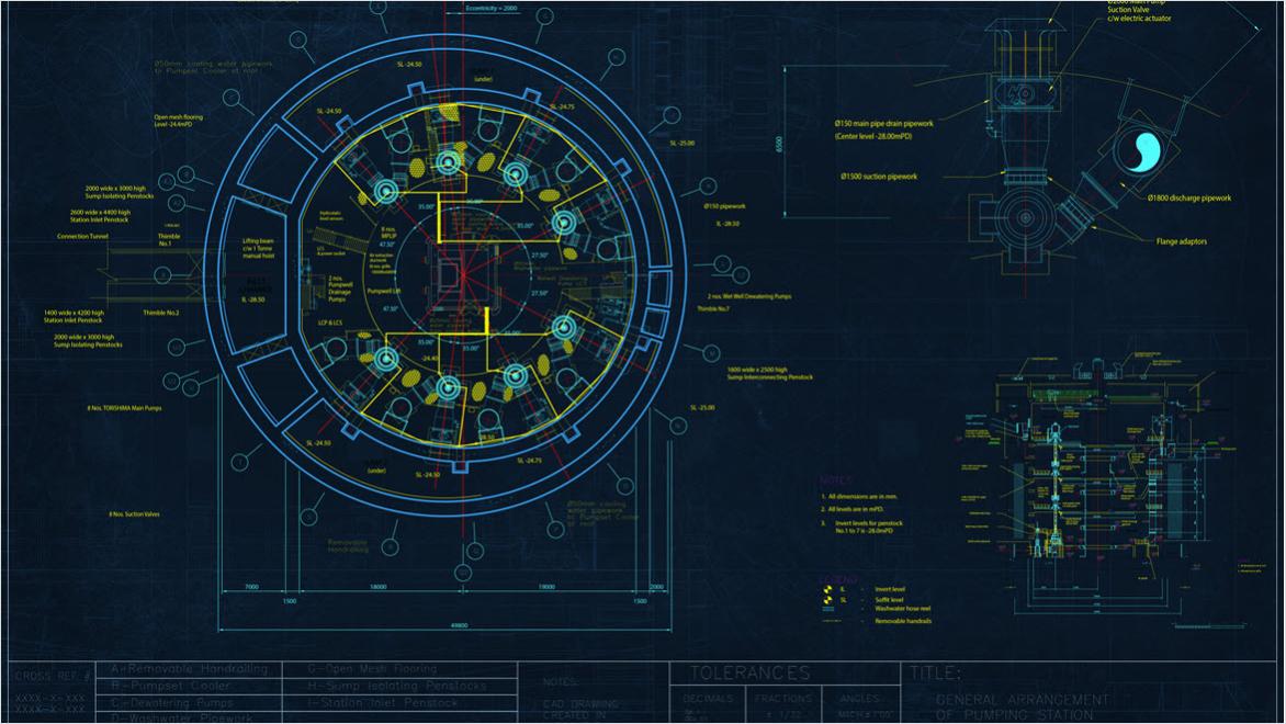
While often used interchangeably, engineering drawings generally focus on detailed technical specifications and fabrication requirements, while technical drawings broadly include disciplines such as architectural, mechanical, electrical, and civil representations. Both share the purpose of accurately communicating design intent.

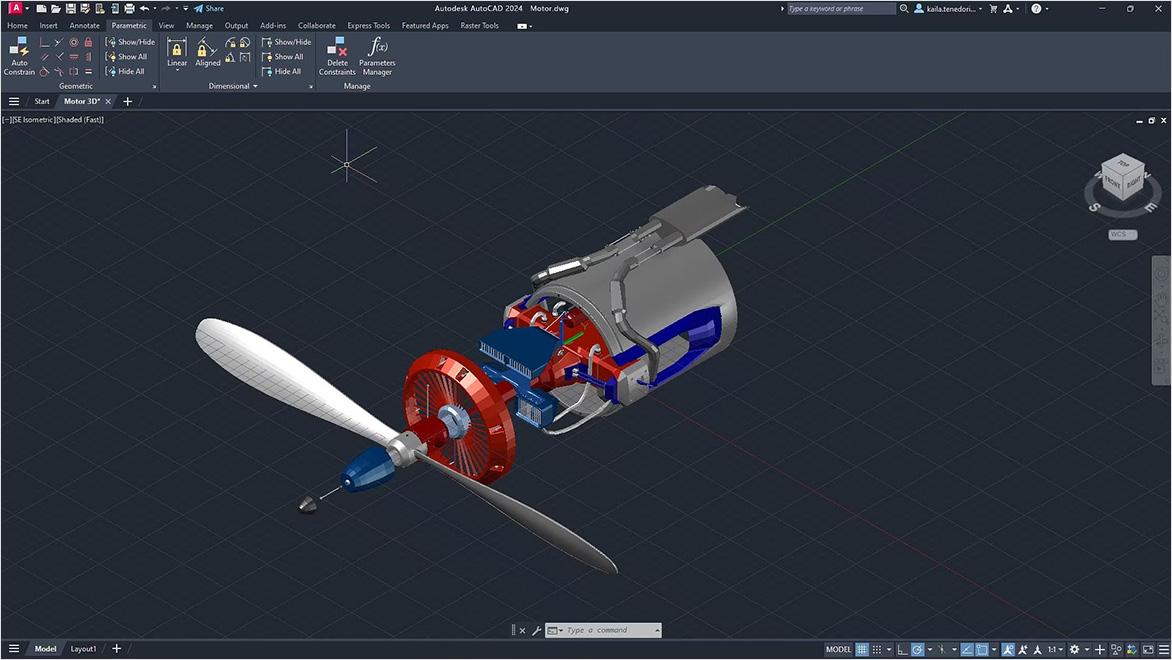
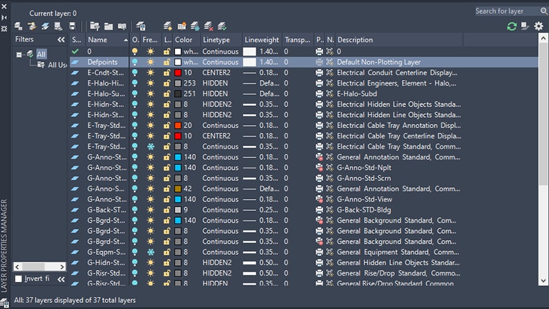
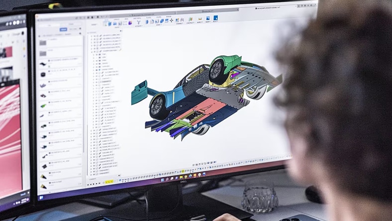
Technical and engineering drawings can be created by hand drafting or digitally through CAD software. Using technical drawing software greatly speeds workflows by automating common tasks, maintaining precise geometry, and simplifying annotation. Autodesk’s technical drawing solutions, like AutoCAD, enable secure work across devices and real-time collaboration among users worldwide.

Technical drawings used for engineering
A CAD drawing of an eco-friendly home takes shape.

Why are technical drawings and engineering drawings important?

Technical drawings, also known as engineering drawings are important during the design and engineering process. Their technical symbols and documentation data like dimensions, tolerances, and materials make sure that the communication between designers and producers is clear and precise. The better that communication is, the more efficient production and operations can be. Also, because technical drawings are standardized in their symbols, measurements, and other data, they can be trusted for keeping production consistent and maintaining quality control. And, due to flexibility in scaling, they allow detailed information to be added to convey 100%-accurate intent. Their data also comes in handy as a record for future reference. 

Using technical drawing software helps to solidify those benefits by helping maintain precision and accuracy and making real-time collaboration between team members and stakeholders easier. The software can also produce realistic 3D visualizations based on the technical drawings to better convey design intent and make informed decisions. This integration streamlines workflows and supports informed decision-making in drawing and engineering projects.

CAD drawing of a pumping station created in AutoCAD LT.

Why Autodesk solutions for technical drawings and engineering drawings?

Autodesk offers a comprehensive suite of solutions designed to streamline the creation, management, and collaboration of technical drawings and engineering drawings. Powerful 2D and 3D CAD drafting tools allow for precise geometric modeling, detailed annotation, and the use of standardized symbols and dimensions essential for engineering accuracy. With features including parametric modeling, dynamic blocks, and layer management, Autodesk solutions help users automate routine tasks, maintain consistency, and update drawings efficiently as designs evolve.

Cloud-based capabilities allow secure work and real-time collaboration across devices worldwide. Teams can communicate design intent clearly and make informed decisions with advanced 3D visualization and photorealistic rendering. Autodesk’s integrated tools also cover specialized disciplines such as mechanical design, architecture, civil, and electrical engineering, supporting the diverse needs of professionals across industries.

Autodesk technical drawing and engineering drawing software

Powerful product design and engineering tools for 3D mechanical design, simulation, visualization, and documentation.


Cloud-based 3D CAD, CAM, CAE, PCB, and PDM software for product design.


Get Inventor + AutoCAD + Autodesk Fusion + more—Professional-grade tools for product development and manufacturing planning.


2D and 3D CAD tools, with enhanced insights, AI-automations, and collaboration features. Subscription includes AutoCAD on desktop, web, mobile, and seven specialized toolsets.


Best-in-class tool for 2D CAD drafting, drawing, and documentation. Subscription includes AutoCAD LT on desktop, web, and mobile.


Plan, design, construct, and manage buildings with powerful tools for Building Information Modeling.


Benefits of using technical drawing software

Technical drawing software transforms design workflows, enhances accuracy, and improves collaboration compared to traditional methods.

Speed and precision

Technical drawing software speeds up the design process compared to hand drafting by automating measurements and alignments. It eliminates the need to draw every line manually. This reduces errors and helps maintain consistent, precise geometry. IT also boosts efficiency so that projects can be completed faster without compromising quality.


Automation and annotation

Modern technical drawing and engineering drawing software automates repetitive tasks like generating bills of materials and inserting standard components. It simplifies managing symbols for architectural, electrical, or mechanical features. Annotation tools enhance documentation of dimensions and tolerances. Layer management helps organize drawing elements for easier editing and visualization.


Parametric modeling integration

Parametric modeling in technical drawing software lets designers create smart 3D models that automatically update associated 2D drawings. This integration streamlines workflows, enabling accurate, detailed, and consistent drawings across multiple views. It supports faster design iterations and improved consistency.


Real-time collaboration

Cloud-based technical drawing software allows multiple users to collaborate in real-time from any location. Teams can securely access, share, and edit drawings on web browsers or mobile devices without complex setups. This boosts communication, speeds decisions, and keeps everyone working on the latest design, minimizing errors and rework.


Types of technical drawings

Technical drawings vary based on the discipline they serve, from buildings to products and more, learn about the most common types of technical drawings from Autodesk.

Mechanical engineering drawing

Mechanical engineering drawings are used to define the requirements for engineering products/components. They serve as technical manuals and as troubleshooting tools for identifying the weak spots in a mechanical design. Mechanical drawings rely on precise mathematical equations to accurately depict the mechanism and its component parts.

Electrical drawing

Electrical drawings are technical documents that depict and notate designs for electrical systems. They convey relevant information about lighting, wiring, power sources, voltage, and capacity. Technicians rely on electrical drawings during a building’s construction or when repairing a building’s electrical system.

Architectural drawing

Architectural drawings are detailed, precise depictions of every aspect of the construction being proposed. Architects use the drawings to visualize ideas and concepts, turn a design idea into a coherent plan for a building, and decide the type of supplies and labor needed for the project.

Structural drawing

Structural drawings are detailed drawings that depict the various members, components, connections, dimensions, etc. that clearly communicate the structural framework necessary for any building or infrastructure project.  These drawings help ensure the project is built to withstand code-required loads and forces.


Civil/site drawing

Civil site drawings, also known as site plans or site layout drawings, are technical drawings that depict the layout and design of a construction site. These drawings provide a visual representation of the site and its various components. These include buildings, roads, parking lots, utilities, landscaping, and other site features.


MEP drawings

MEP drawings, also known as mechanical, electrical, and plumbing drawings, are technical drawings that illustrate the layout and design of the mechanical, electrical, and plumbing systems within a building or infrastructure project. These drawings provide detailed information about the installation and coordination of these systems.


Industries that use technical drawings and engineering drawings

Technical and engineering drawings are essential tools used across various industries to convey precise design and construction information. 

Architecture

Architecture

Architects use technical drawings to create detailed blueprints and plans for buildings and structures. These drawings help visualize design concepts, specify materials, and communicate construction requirements to contractors and builders.


Robotic machines in manufacturing

Manufacturing

In manufacturing, technical drawings represent products and components with precise dimensions and specifications. Engineers and designers use these drawings to guide fabrication, assembly, and quality control processes.


Civil Engineers looking at plans

Civil Engineering & Construction

Civil engineers rely on technical drawings to design infrastructure such as bridges, roads, and utilities. These drawings provide detailed plans that make sure projects meet safety codes, material requirements, and structural integrity.


Engineer working on plane turbine

Aerospace & Automotive

Technical drawings in aerospace and automotive industries depict complex parts and systems, enabling precise design, testing, and production. They assist in simulation, performance analysis, and regulatory compliance throughout product development.


Technical drawing elements
Geometric dimensions and tolerances (GD&T) are easier to manage within software.

What are the basic elements of technical drawings?

Technical drawings contain many basic elements that are easier to change and manage when working within technical drawing software. For example, it can be much more precise, and faster, to manipulate the basic lines, curves, and arcs of technical drawings within software. Also, the geometric dimensions and tolerances (GD&T) and other annotations vital for creating accurate drawings are easier to manage within software, which can automate their updated values when you change the drawing. Along the same lines, symbols within technical drawings—like architectural, plumbing, or electrical symbols—represent different features for objects within the drawing, and software can help manage and assign symbols.

Engineering drawing and technical drawing software also makes it easy to control the status and properties of sections views and layers. These often contain different groupings of objects or components that the software can hide, make transparent, and filter.

Technical drawing software features

Discover top technical drawing tools and features available with Autodesk software.

2D drafting for technical drawings

2D drafting

With 2D CAD drafting, architects, engineers, and product designers can create precise technical drawings faster, getting results quickly with technological assistance like inserting commonly used building parts, adjustable line styles, easy annotation, reusable design elements, dynamic blocks, and real-time collaboration with multiple users.


Layer management for technical drawings

Layer management

When making technical drawings in AutoCAD software, layers help manage all the objects in a drawing. The Layers Properties Manager lets you control layer filters and layer display states; create, search, and delete layers; make objects transparent; edit layer properties; and more.


Parametric modeling for technical drawings

Parametric modeling

With parametric modeling, 3D models contain dimensions, constraints, and other variables that intelligently update the model when changes are made. Autodesk’s technical drawing software includes parametric modeling that uses the shapes and dimensions from 2D technical drawings. The models can also be used to generate customized 2D drawings, highly annotated with materials, part numbers, dimensions, and other documentation.


Rendering and visualization for technical drawings

Rendering and visualization

Autodesk’s technical drawing software includes 3D rendering and visualization features for producing highly accurate still images and animations from computer models and technical drawings. Rendered images can include visual effects like shading, texture mapping, shadows, reflections, and other details that make them appear photorealistic. This visualization helps designers and product developers present their projects to clients and market products to customers. 


Technical drawing using Autodesk solutions
Image courtesy of Briggs Automotive Company Ltd.

Drawing and engineering

Drawings and engineering go hand-in-hand because engineering relies on drawings as a precise and universal language to communicate complex design ideas. Drawings serve as essential tools throughout the engineering process—from conceptualization, through design refinement, to manufacturing and assembly. They provide detailed information about dimensions, materials, and assembly instructions that enhance accuracy, efficiency, and quality in the final product. Without clear technical and engineering drawings, the complex collaboration across disciplines and the translation of creative ideas into physical reality would be impossible.

Real-world applications of technical drawings and engineering drawings

See how customers are using Autodesk software to create technical drawings.

Technical drawings and smart design

GÜRALP

Technical drawings and smart design

A designer and manufacturer of crane systems, Güralp delivers specialized hoists and lifts to customers in more than 65 countries. Learn how Güralp adopted the Autodesk Product Design & Manufacturing Collection for its design and technical drawing software, which helped to speed up product development, manage data, reduce defects, streamline processes, and focus on eco-friendly design.


Technical drawings and infrastructure

HR WALLINGFORD


Technical drawings and infrastructure

To build a better flood management system for Florence, Italy, water infrastructure expert HR Wallingford turned to Autodesk InfraWorks ICM hydraulic and hydrologic software to model the effects of high-intensity rainfall on the city. In the process, the project team consulted and digitized technical drawings over a century old from medieval-era buildings to gain insight into the urban sewer network.


Technical drawings to 3D rendering

YSA DESIGN

Technical drawings to 3D rendering

A leading interior designer for cruise ships, YSA Design switched from handling its technical drawings in 2D drafting software to 3D BIM modeling in Autodesk Revit. The change created a single source of truth from a central model and made workflows and client communication smoother, shortening 3D visualization time from weeks to seconds.


LIXIL

Cloud-based technical drawings

When this global manufacturer of home water products (showers, faucets, toilets, etc.) created an automated drafting system for quickly processing technical drawing, its popularity caused problems with scaling up the system. Integrating the system into the cloud with Autodesk Platform Services made it scalable, reduced technical drawing drafting time by 15–30%, and cut associated costs.


Rendering of a BAC Mono automotive detail--the pedal box assembly with drawing.
Image courtesy of Briggs Automotive Company Ltd.

Reading and interpreting technical drawings

Reading and interpreting technical drawings is essential for maintaining manufacturing and construction accuracy. Key elements such as title blocks provide crucial information including drawing identification, project details, revision history, and scale. Revision blocks track changes so that stakeholders work with the latest versions. Bills of materials list all components needed, helping manage resources effectively.

Drawing keys explain symbols and notations, while scales make sure that dimensions are accurately translated from drawings to real-world sizes. Together, these elements provide clear, detailed guidance that minimizes errors, supports quality control, and facilitates efficient project execution.

GD&T in Autodesk Inventor

Geometric dimensioning and tolerancing (GD&T) in technical drawings

Geometric dimensioning and tolerancing (GD&T) is a standardized system of symbols and rules used on technical and engineering drawings. It precisely communicates the design intent, specifying the allowable variation in size, shape, orientation, and location of part features. GD&T ensures that parts fit and function correctly even with manufacturing variations by clearly defining tolerances, reducing guesswork, and improving quality and interchangeability. This system enhances traditional dimensioning by focusing on functional requirements, enabling more accurate manufacturing and inspection processes.

Technical drawing software resources

Learn more about technical drawing software with these helpful resources from Autodesk.

Quickly learn how to generate a printable or exportable 2D drawing to your specifications from a 3D design in Autodesk Fusion technical drawing software.

Learn what CAD drawing software can do for AEC and manufacturing businesses, how others are using it, and which CAD and technical drawing software solutions will work best for you.

Both students and educators can receive free educational access to Autodesk technical drawing software such as TinkercadAutodesk FusionRevit, AutoCAD, and much more. Find out how today.

Startups and nonprofits committed to using design to do environmental and social good can apply to Autodesk’s Technology Impact Program to receive free software for technical drawing, photogrammetry, 3D design, engineering, visualization, and simulation.

Take this professional AutoCAD course to build technical drawing software skills in templating, advanced object creation and editing, measurement tools and methods, Design Center workflows, and more.

Frequently asked questions (FAQ) about technical drawing software

Learn more about technical drawing software and tools with these top questions frequently asked by users.

What are the five main types of technical drawing?

The five main types of technical drawing cover mechanical, civil, and electrical engineering; manufacturing assembly; and architecture. Designers and engineers in each discipline all produce and use precise technical drawings that convey how an object or structure functions and/or how to construct it.

What is sectioning in technical drawing?

Sectioning in technical drawing shows the internal configuration of a part or object, as if the object has been sliced through. When a technical drawing is rendered in sections, it reveals the interior construction of an object and the relationship between different parts or components and space. The Autodesk Architecture, Engineering and Construction Collection delivers integrated tools for streamlined 2D and 3D technical drawing.

What is perspective drawing in technical drawing?

Perspective drawing is a way to represent 3D objects on a flat surface. Using perspective drawing conveys depth, space, and extension of an object, tool, part, or building. Autodesk Inventor software makes it easy to apply perspective to a custom technical drawing view.

Why is technical drawing important in the manufacturing industry?

Detailed technical drawings communicate the design intent of the item to be manufactured and assembled. They help the manufacturer understand how to build or construct something to a specific size, form, and function so it will work correctly. Technical drawing details help streamline the manufacturing process in two ways: Reducing the time spent from design cycle to production and eliminating errors and waste associated with missing or incomplete manufacturing information.

How do you read technical drawings?

To read technical drawings, refer to the many information blocks provided on the drawing.


The title block, located on the bottom right corner of the drawing, includes a description of the drawing, information about the materials to be used, scale, tolerances, size, part numbers, and more. The revision block, located in the upper right corner, explains revision details or changes made to the original drawing. The bill of materials block, above the title block or on the upper left corner, includes a list of all the items or quantities of materials needed to assemble the object or structure. The drawing key explains various symbols and lines that can identify the different features of an object or structure. Finally, the scale number will explain the scale at which to produce the drawing. For example, 1:1 means the drawing represents the actual size of the object, and 100:1 means the actual object is 100 times the size of the drawing.

What is pattern development in technical drawing?

Pattern development in technical drawing is the creation of a flat representation of a three-dimensional object. True pattern development uses parallel lines, radial lines, or triangulation so that every surface on the pattern is the same size and shape as the corresponding surface of the 3D object.

Why is technical drawing important to architecture?

Technical drawing is an important component of architecture because it provides insight into what the final structure will look like and its relationship to its surroundings. Architecture technical drawings illustrate a finished structure, show exact dimensions for construction, present how different parts of the structure fit together, diagram the arrangement of species within the structure, and reveal mechanical and material details necessary in constructing the project. Autodesk’s architecture software empowers efficient and seamless technical drawing for architects.

What are the differences between architectural and engineering drawings?

Both architectural drawing and engineering drawing are types of technical drawing used on construction projects. Architects produce architectural drawings to convey their design intent for a building, including layout plans for floors, sections, elevations, and exterior and interior details.


The difference between architectural and engineering drawings is that engineers create technical engineering drawings that focus on the technical details of the building’s structure and MEP (mechanical, electrical, plumbing).


Both types of technical drawing contribute to a construction project’s success.

Can I use technical drawing software for both 2D and 3D designs?

Yes, you can use technical drawing software for both 2D and 3D designs. Many programs combine the capability of both 2D and 3D technical drawing into one software, such as Autodesk AutoCAD. For a more cost-effective way to focus on just 2D design, AutoCAD LT uses innovative automation features to accelerate 2D technical drawing, drafting, and documentation.

What is technical drawing drafting?

Technical drawing drafting, also known simply as drafting or technical drawing, is the precise and detailed process of creating graphic representations that convey how an object functions or is constructed. These drawings are made to scale and use standardized symbols and conventions to ensure clarity and unambiguity. Unlike artistic drawings, the focus is on accuracy and clear communication, providing essential information for manufacturing, construction, or engineering. Drafting can be done manually or with modern CAD software, serving as a critical tool for designers, engineers, and builders to translate ideas into workable plans.

What is the difference between 2D and 3D technical drawings?

2D technical drawings show length and width on a flat plane using multiple views to represent an object, focusing on precise dimensions and layout. 3D drawings add depth, creating realistic models that can be rotated and viewed from all angles. 2D technical drawings are  simpler and faster for basic projects. 3D engineering drawings offer better visualization, reduces errors, and supports complex design and testing.

How do technical drawings support quality control in manufacturing?

Technical drawings support quality control in manufacturing by providing precise specifications, including dimensions and tolerances, making sure that parts are made to exact standards. They eliminate ambiguity, reduce errors, and serve as a reference for inspection and verification, This aids in maintaining consistency and high product quality throughout production.

What are common errors to avoid in technical drawing and drafting?

Common errors to avoid in technical drawing and drafting include:

  • Using incorrect units or scales, leading to inaccurate measurements.

  • Overloading drawings with excessive details or symbols, causing confusion.

  • Neglecting proper line weights, reducing clarity.

  • Drawing at wrong angles, resulting in misalignments.

  • Failing to use consistent formats when sharing files.

  • Ignoring or misapplying tolerances and dimensions.

  • Missing essential views or annotations.

  • Incomplete or unclear revision tracking.

Avoiding these mistakes improves accuracy, readability, and communication in technical drawings.


How do industry standards and symbols impact the readability of technical drawings?

Industry standards and symbols greatly enhance the readability of technical drawings by providing a consistent, universal language that all professionals can understand. They help maintain clear communication by standardizing text sizes, line types, symbols, and annotations, which prevents misinterpretation and errors. This consistency makes drawings easier to read, reduces confusion, and improves collaboration across teams and industries.

What are the most common types of technical drawings and engineering drawings used in different industries?

The most common types of technical and engineering drawings used across industries are:

  • Architectural Drawings: Show building layouts, elevations, sections, and details for construction planning.

  • Structural Drawings: Detail the framework and load-bearing elements of buildings and infrastructure.

  • Mechanical/Engineering Drawings: Define specifications for manufacturing parts, machinery, and mechanical systems.

  • Electrical Drawings: Illustrate wiring, circuits, and electrical system layouts for installation and maintenance.

  • Piping and Instrumentation Diagrams (P&IDs): Used in process industries to detail piping and control systems.

  • HVAC Drawings: Map heating, ventilation, and air conditioning systems for buildings.

  • Assembly Drawings: Show how components fit together in products for manufacturing and assembly.

  • Isometric and Orthographic Drawings: Provide 3D-like perspectives or multiple flat views for better visualization and detail.

These drawings serve specific functions in construction, manufacturing, engineering, and industrial processes, for precise communication and execution of designs.


See more FAQ