& Construction

Integrated BIM tools, including Revit, AutoCAD, and Civil 3D
& Manufacturing

Professional CAD/CAM tools built on Inventor and AutoCAD
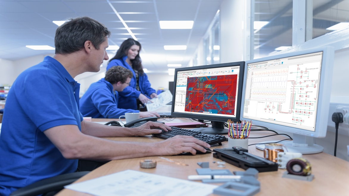
Electronic design is developing and integrating electronic components to achieve desired functionality or performance in a product or system. This includes research, creating schematics, designing printed circuit boards (*) (PCBs), and building prototypes (*) to test and optimize the design.
Electronic design is a critical component of the product development process, and it requires a combination of technical knowledge, creativity, and problem-solving skills. Electronics design is crucial in various industries, including consumer electronics, telecommunications, automotive, aerospace, medical devices, and more. It requires expertise in circuit theory, electronic components, signal processing, and electromagnetic compatibility (EMC). As well as considerations for power consumption, size, and cost constraints to make sure that the final product meets the necessary standards and regulations.
*All links point to the US site.
Electronic design automation (EDA) is a software category for designing electronic systems, including circuits and printed circuit boards. Using electronics computer aided design (ECAD) solutions (US Site), engineers can automate various stages of the design process and have access to create, analyze, simulate, and verify electronic circuit systems.
EDA software plays a crucial role in designing, analyzing, and optimizing electronic systems. It enhances productivity, improves design quality, facilitates collaboration, and ultimately contributes to developing innovative and efficient products in the electronics industry. By catching errors early and streamlining the design process, engineers can minimize costly rework, shorten time-to-market, and improve product reliability.
Understanding the specifications and functional requirements of the electronic system or device that needs to be designed.
A logical circuit diagrams (US site) that represents the interconnections and required components of the electronic circuit.
Choosing electronic components based on their specifications, performance characteristics, availability, and cost.
Transferring the circuit diagram into a printed circuit board (US Site) (PCB) layout. Involves arranging electronic components, traces, vias, and other elements on the board for proper functionality and electrical performance.
Conducting various tests to validate the design, including functional testing, electrical testing, and performance evaluation to assure component functionality.
EDA tools export the necessary manufacturing files, including ODB++, Gerber files for PCB fabrication, bill of materials (BOM), and assembly instructions to streamline production and help manufacturing accuracy.
Autodesk Fusion combines electronics and mechanical design, simulation, collaboration, and machining connecting the entire product development process in one software solution.
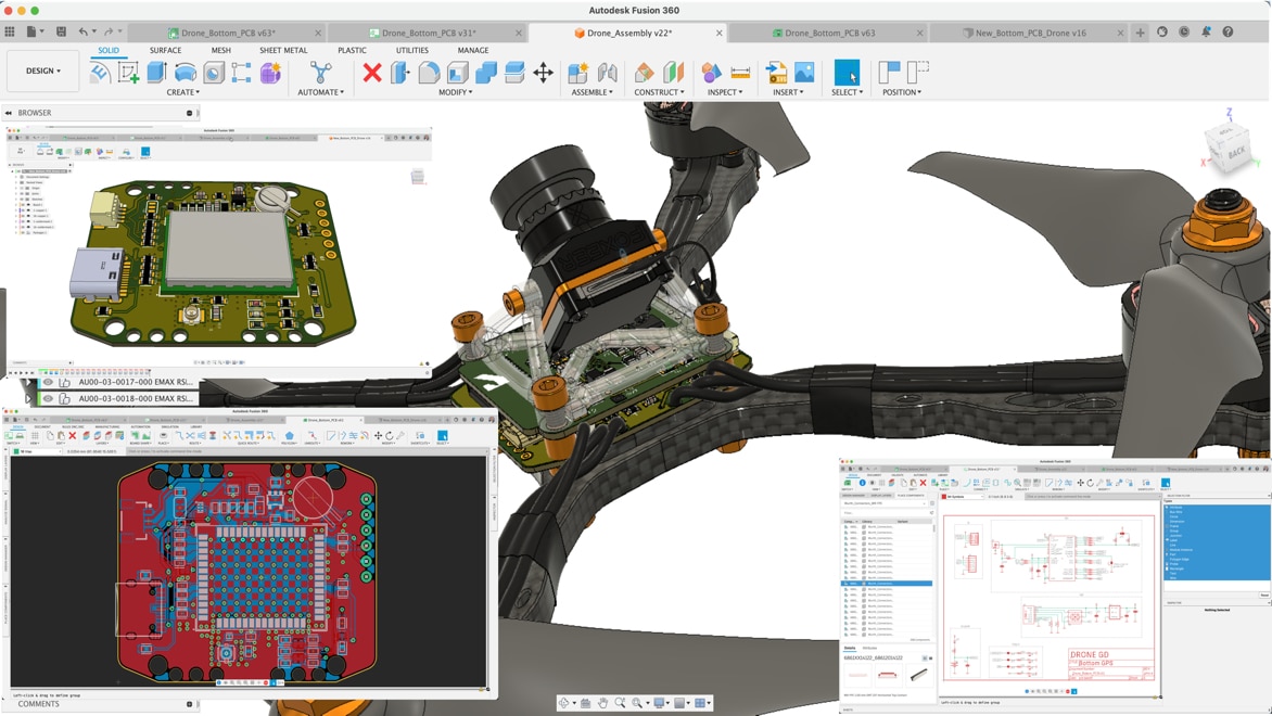
Autodesk Fusion electronics offers a unified approach to both ECAD and MCAD design workflows (US Site) that puts these seperate design domains in one integrated environment. Your ECAD data is the exact same data set as your MCAD data eliminating the need for multiple file exchange formats including STEP, IGES, IDF, and more.
Truly integrated ECAD/MCAD (US Site) software eliminates the need for separate software solutions. Your PCB data is your mechanical data.
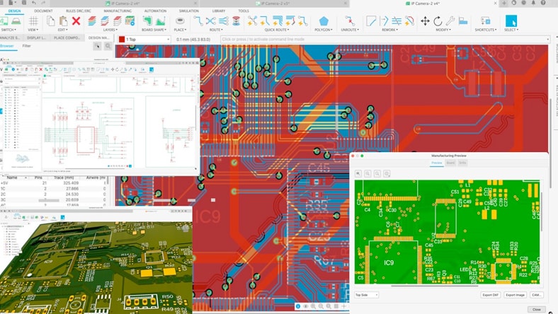
Gain access to a comprehensive environment for schematic design, PCB layout, component placement, and routing (US Site).
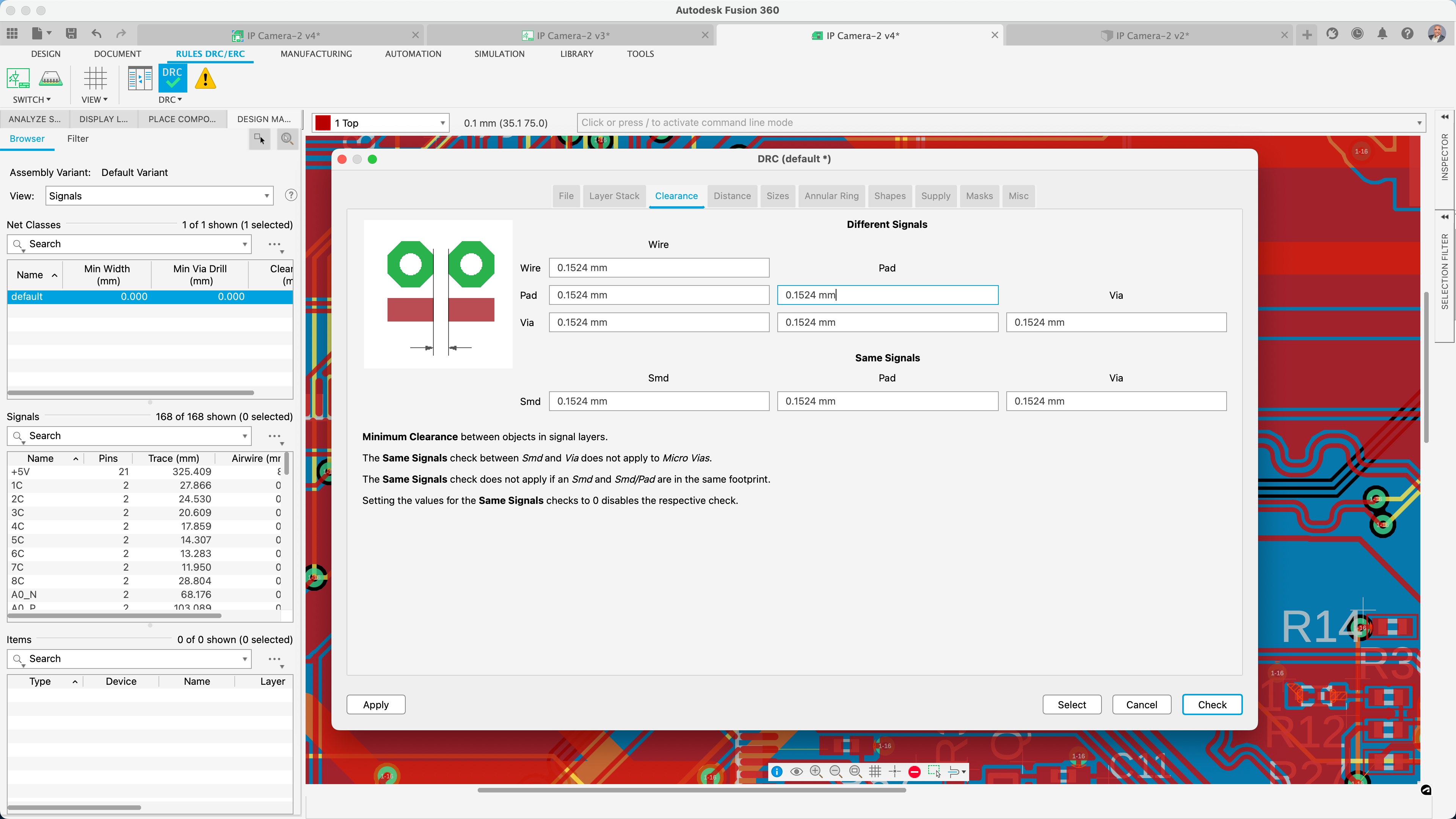
The built-in design rule checking (DRC) and validation tools in Autodesk Fusion electronics make sure that designs meet industry standards and design constraints.
A single cloud solution allows for effective collaboration (US Site) and that every stakeholder is part of the product development cycle. Design changes are automatically managed to enable you to revise your board shape, component placement update, or modified enclosure.
Bring your designs to life with automation. Use schematic design, PCB layout, and routing capabilities built into Autodesk Fusion.
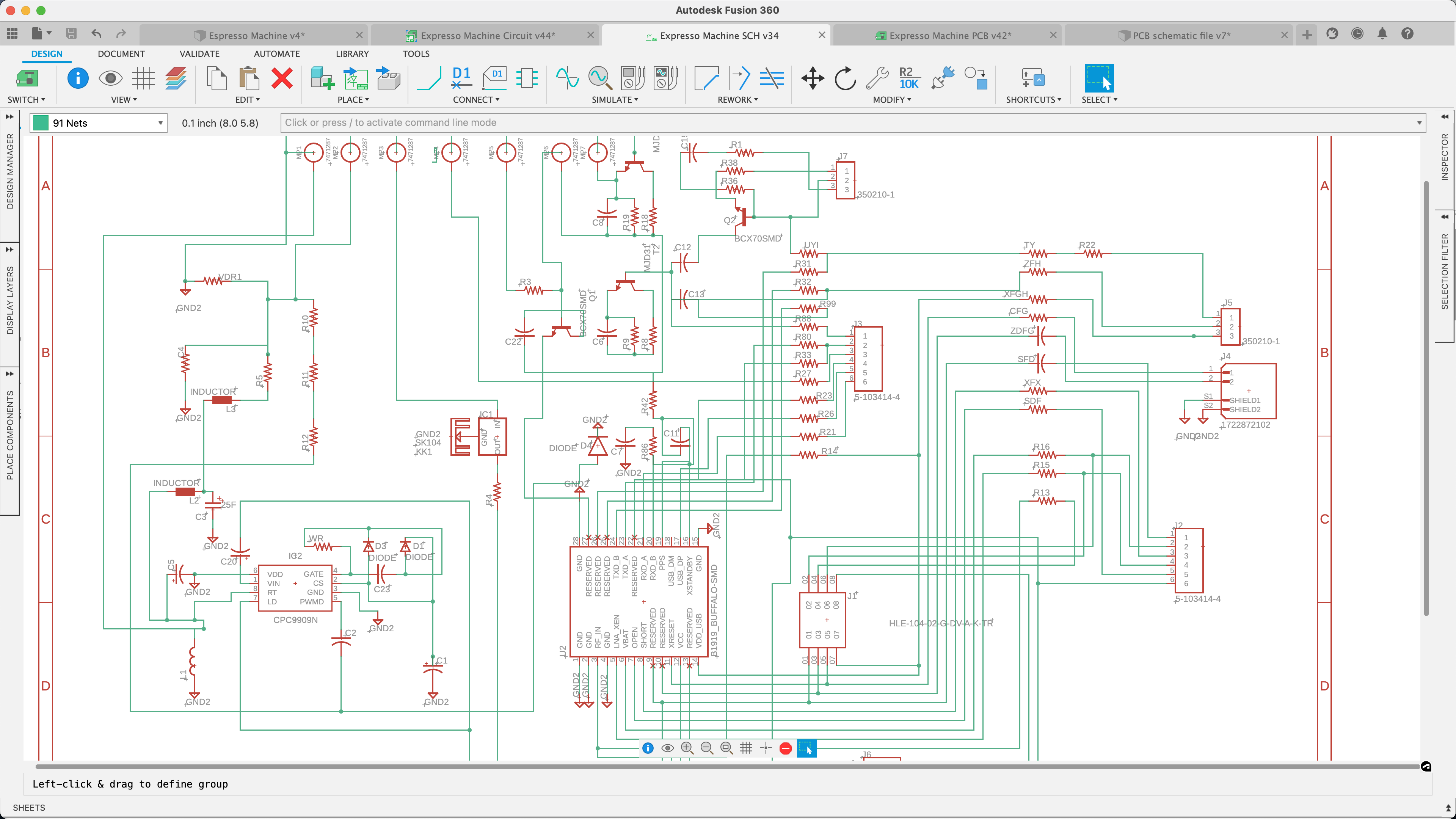
Save valuable design time with a complete set of schematic tools. Get access to thousands of components. Interconnect circuits and create custom attribute assignments.
The PCB editor lets you connect your ideas together in the shortest time possible. Even the layout of dense boards is possible with a complete set of PCB layout tools.
Stay true to your manufacturing requirements with customizable design rules.
Export the manufacturing files in ODB++ or Gerbers, drill files, and assembly files within a few clicks.
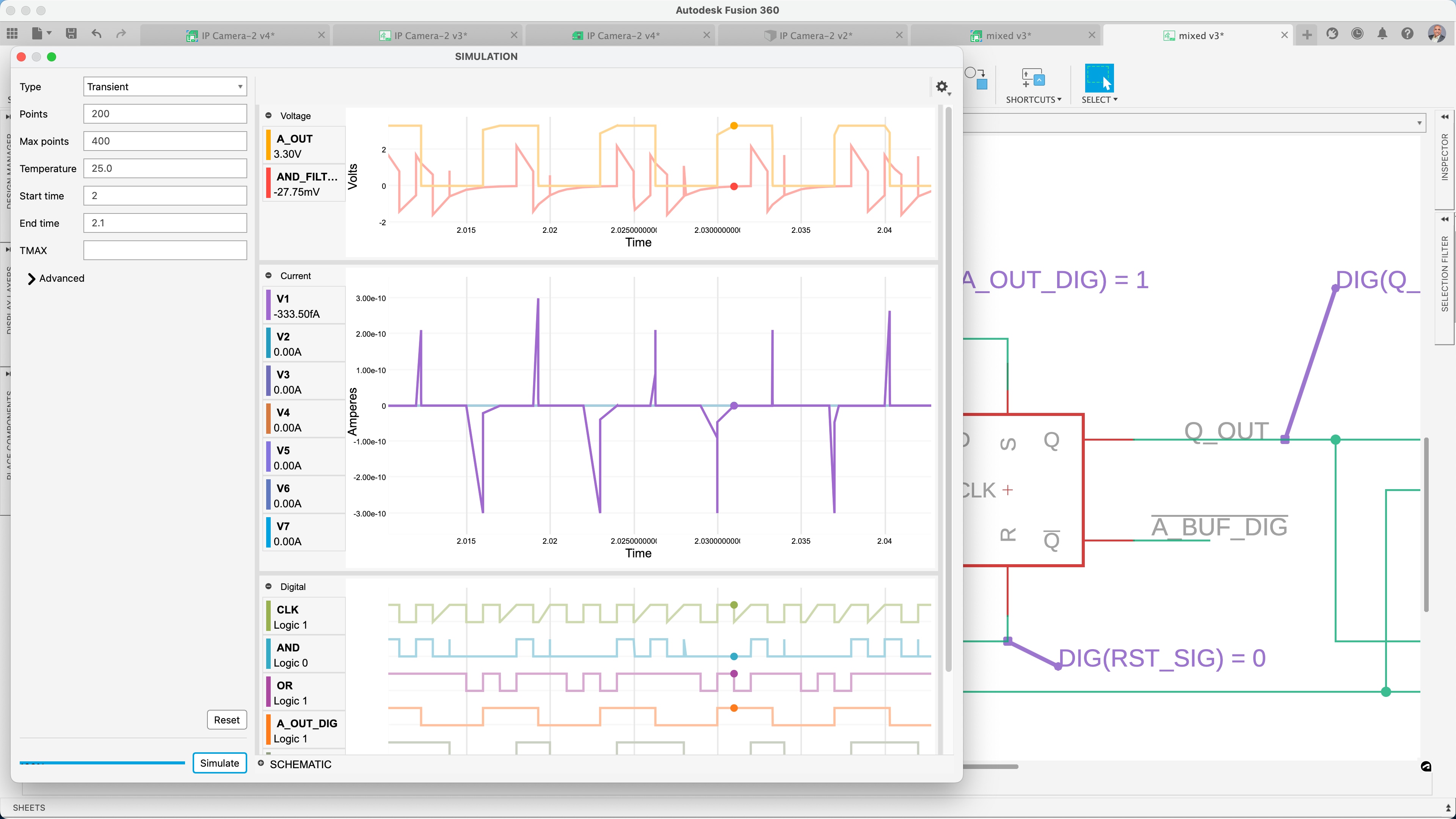
Use our Spice Simulator to map components and verify that the expected results are being met.
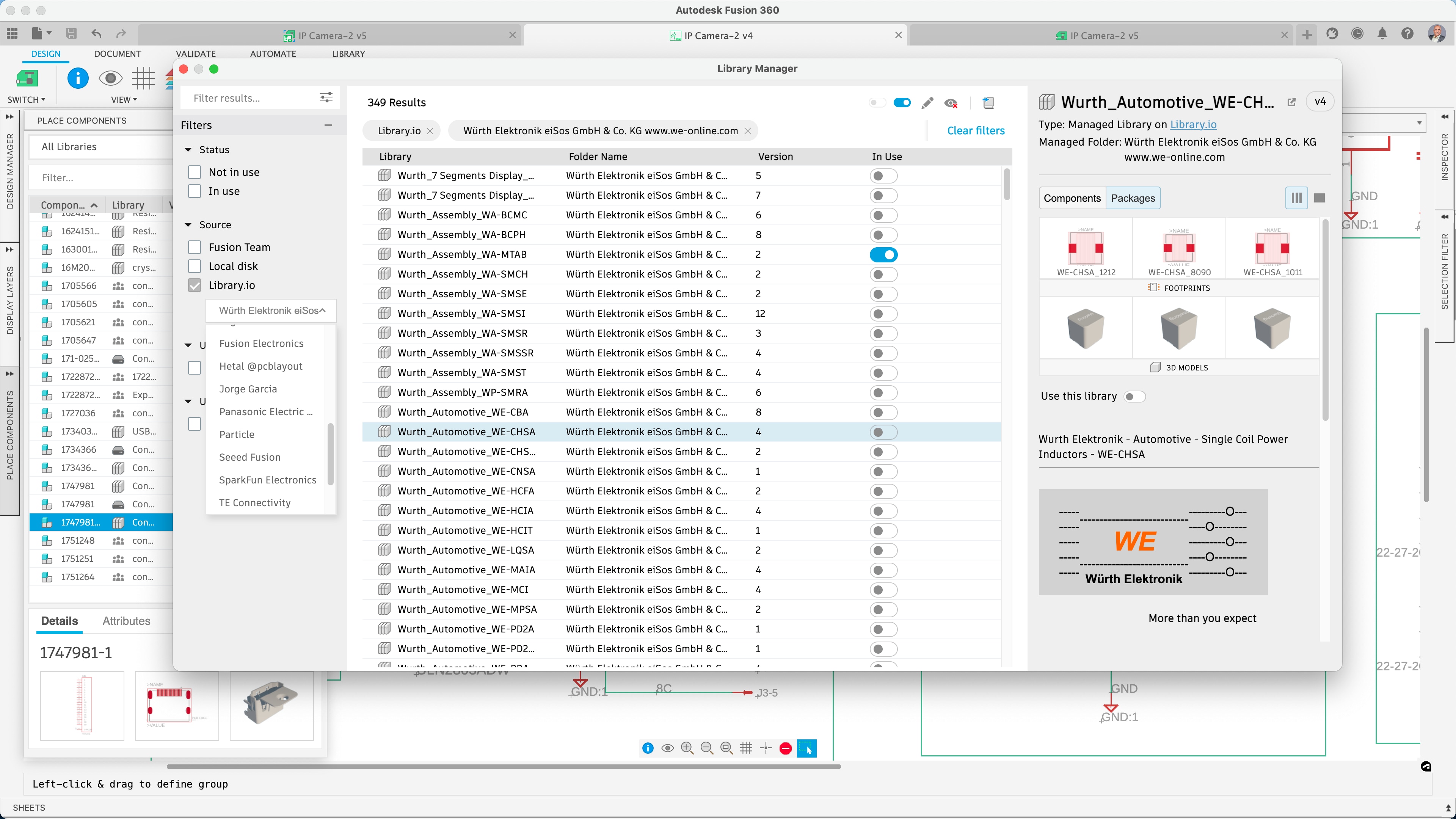
The significant amount of ready-to-use component assets in the libraries and the component calcultors will help you focus on the design.
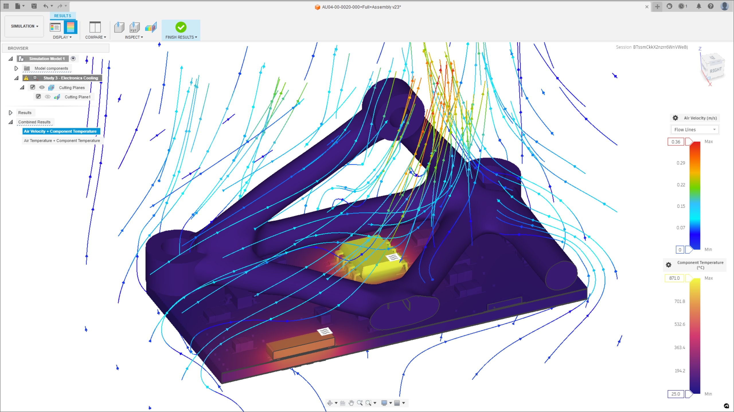
The e-cooling analysis features in Autodesk Fusion allow users to simulate and evaluate the thermal behavior of their designs.
Optimize PCB design electromagnetic performance by controlling the impedance of every critical transmission line.
This electronics for beginners guide will walk you through the basics of electronics design to kick off your first project.
ECAD/MCAD (US site) integration is no longer an option in product design. See how Autodesk Fusion can make complex electromechanical workflows easy without file conversion.
Autodesk Fusion Electronics is a better PCB design solution because it seamlessly integrates multiple tools. This enables designers to work within a single, unified environment and eliminates the need to switch between various applications.
Learn why you should start using Autodesk Fusion electronics and workflows that will speed up your design time.
Manage your design, not your tools. Enjoy the most unified and connected ECAD MCAD experience for your PCB with Autodesk Fusion Electronics.
The Autodesk Fusion Signal Integrity Extension, powered by Ansys, unlocks more PCB/electronics signal integrity tools and capabilities, allowing you to run electromagnetic analysis on critical signals within your PCB.
Autodesk Fusion electronics offers compatibility through common file formats, allowing you to exchange designs and collaborate with other EDA tools.
Yes, Autodesk Fusion electronics provides tools and features that allow you to define and design your own custom electronic components and footprints to use in your PCB designs.
Yes, Autodesk Fusion electronics allows you to test your designs to make sure they will survive real-world conditions. Simulate your products digitally, reducing the cost of prototyping by using fully validated solvers.
Yes, Autodesk Fusion electronics includes built-in sharing and collaboration tools. These features make it easy to collaborate with team members, clients, and suppliers in real time. Thus, streamlining the design process and fostering a more efficient workflow.
Yes, you can use Autodesk Fusion to create 3D models of your PCB (Printed Circuit Board). Autodesk Fusion is a powerful 3D modeling software that supports the creation of both mechanical and electronic designs. From a 2D circuit board, you can create a 3D board by clicking Switch > Push to 3D PCB. In the 3D PCB toolbar, you can move components, flip them to the opposite side of the board, add holes in the board, and push changes to the 2D board, to keep both documents synchronized.
If the 3D board was created independently, a tool is provided to link the 3D design to a 2D PCB, if a suitable design exists.
